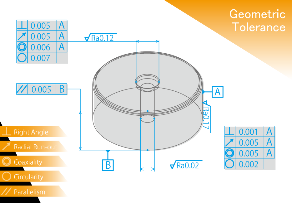
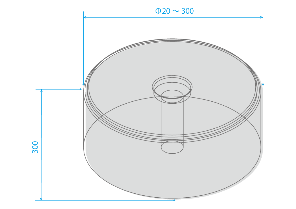
The left figure shows the limit of geometric tolerance that can be manufactured by HIRAOKA Alloy. If higher precision than this is required, deviations will occur. Although there may be cases where it can be done by chance, it is not always possible to achieve the required accuracy. For parts formers, the required geometric tolerance is within 0.01. This accuracy requirement is a standard part of our daily routine. Even if there is no indication of geometric tolerance, we manufacture dies to within 0.01. Our manufacturing department must be able to achieve accuracy within 0.01 on general-purpose machine tools, not just NC machines. Our motto is to stick to the basics.
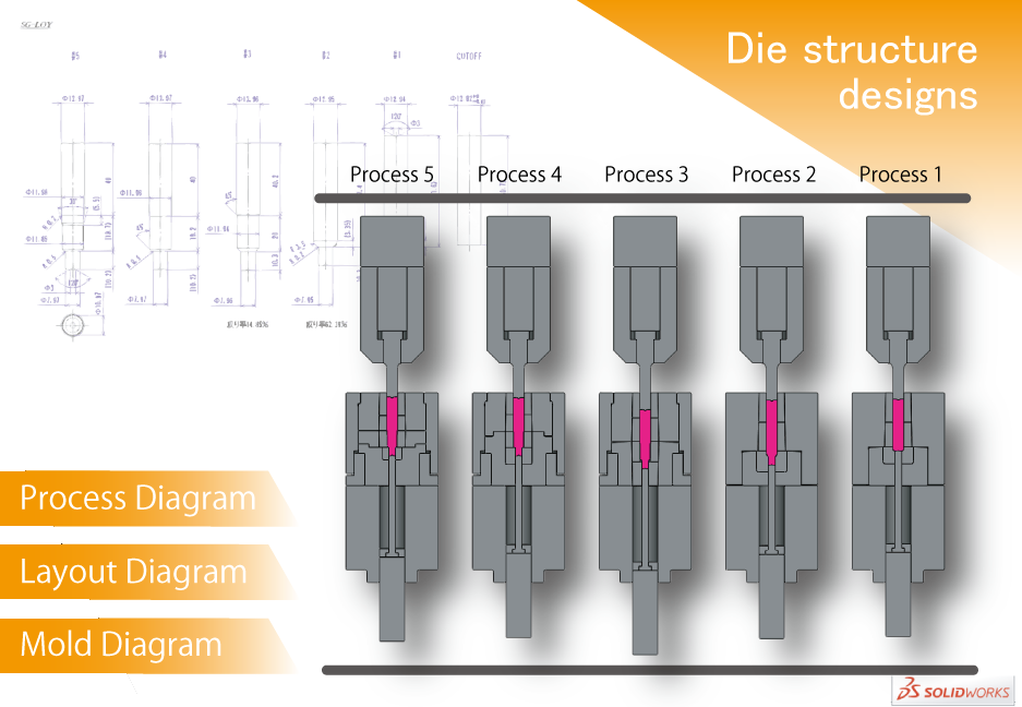
Things required in die structure designs. The first is commercialization, the second is mass production, and the third is cost reduction of manufacturing unit price. These three must be satisfied simultaneously. The process to satisfy these three requirements includes process design, die design, and assembly drawing design.
1. Improvement of material particle flow (fiber flow) is the first priority. A precise shape that allows metal particles to flow without stagnations required for the die to reduce the load on the die and increase its service life. The flow of metal is the same as the flow of water; where there is stagnation, debris will settle.
2. Optimization of blank shape and review of molding methods, etc. To complete the product, it needs to go through a number of processes to shape it into an ideal form. This means that we must be careful not to apply load to the product at the previous process. How can we form the ideal shape without placing a load on the next process, and how can we satisfy dimensional accuracy? With our long years of experience and computer simulations (forging analysis software), we are able to confirm the validity of our designs, and design processes that thoroughly pursue both accuracy and strength.
Once the drawings are completed, a meeting is held within the design group to conduct the verification process.
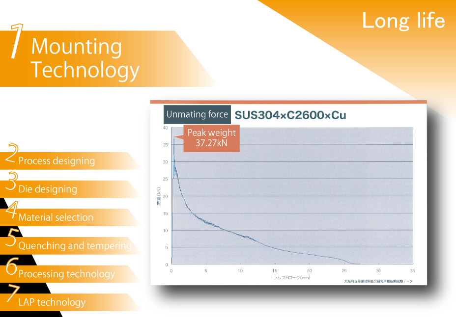
Since the late 1960's, our company has been mainly engaged in carbide dies for long bolts and bicycle parts, which are formed by heading with a long bolt former and a half diameter double header. We have inherited the same technology and have been meeting the needs of our customers for longer service life with one-of-a-kind tungsten carbide press fitting, just like a craftsman making shoes, instead of standardizing the clamping allowance (press fitting ratio). In recent years, we have been using analysis software to diagnose mold stress and reflect the appropriate material, hardness, and clamping allowance (press-fit ratio) in our designs.
Simply put, no compromise. It boils down to this. In order to maintain and improve this quality, we practice thoroughgoing tidying, setting in order, and cleaning activities (3S improvement activities) on a daily basis. Of course, we take data on surface properties after LAP and conduct traceability to ensure consistency with mold life for feedback.
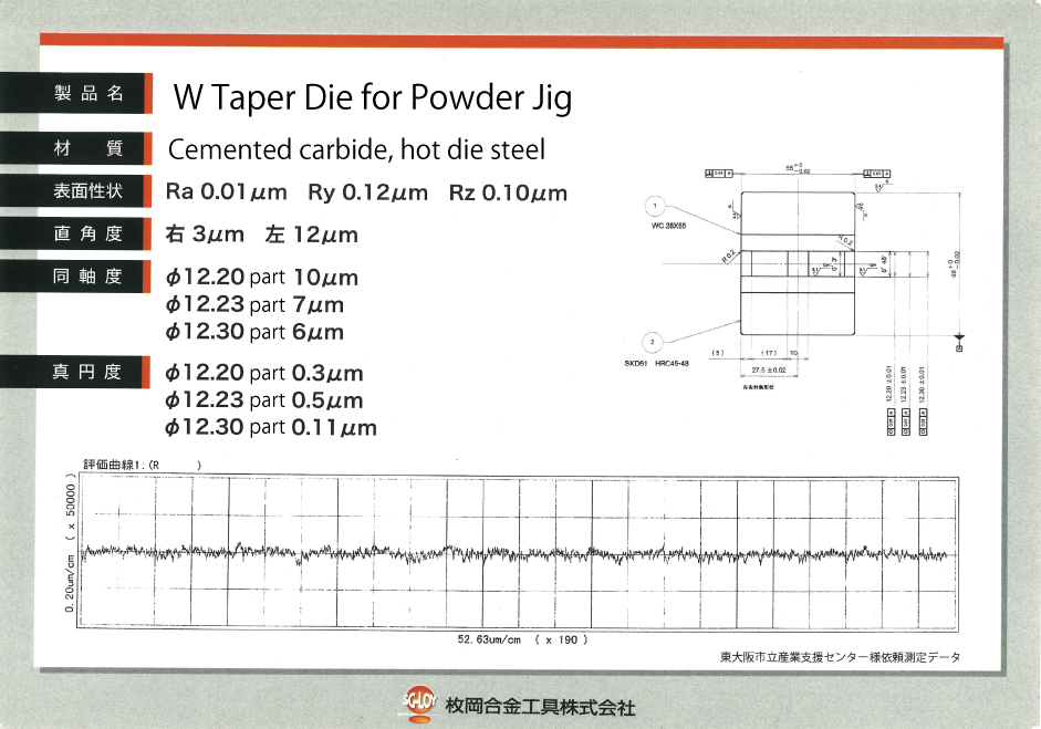
Cemented Carbide, Daido Steel and Hitachi Metals Hot Dies Steel, Hitachi Metals Powdered High Speed Steel
Various PVD coatings CVD coating (carbide only)
Mold outer diameter from Φ20 to Φ300 that can be manufactured, up to 300L in total length